
Ignition/ TXRX Test
1) Connect voltmeter to alternator #1 per Fig 1. Turn vehicle start switch to the run mode.
(Do not start engine). Verify voltage is present on ignition terminal. Connect voltmeter to Alternator #2 per Fig 1. Verify voltage is present on ignition terminal.
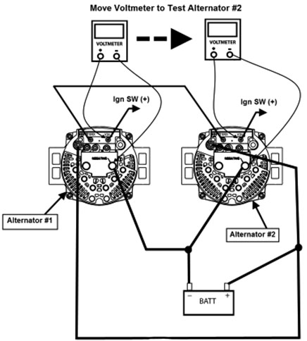
Fig 1
If voltage is not present, troubleshoot the ignition circuit. Do not continue until voltage is present at the alternator ignition terminals.
2) Turn off vehicle start switch.
3) Check continuity of TXRX wire connecting Alternator #1 to Alternator #2.
See Fig 2 for connection of voltmeter.
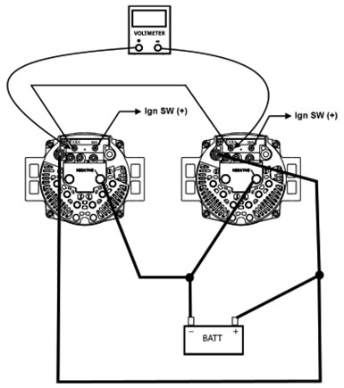
Fig 2
If continuity is not present troubleshoot the TXRX wire.
Do not continue until continuity is present in the TXRX wire.
Alternator Performance Test No Load (Alternator 1)
1) Before you begin with the steps below, make sure the batteries have been properly tested and are at least 75% charged. Otherwise, any electrical tests you conduct on the charging system will be inaccurate.
With the surface charge removed from the batteries, battery voltage should be (12.45V or greater on 12V systems) and (24.9V or greater on 24V systems. If battery voltage is less than 12.45V or 24.9V charge or replace the batteries.
2) Connect voltmeter to Alternator #1 output terminals and ammeter to Alternator #1 positive output cable. Disconnect Alternator #2 ignition and TXRX wire and insulate to prevent shorting.
See Fig 3 for proper connection of voltmeter and ammeter.
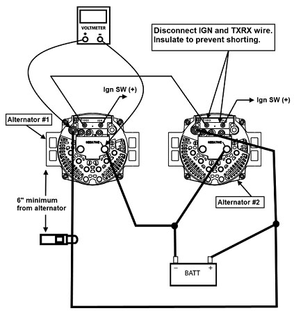
Fig 3
Note: Make sure ammeter is at least 6” (15cm) away from alternator to eliminate the possibility of faulty readings.
3) Make sure voltage is present at the alternator’s output terminals. If voltage is not present correct problem before proceeding.
4) Start engine and operate at 1500 RPM.
5) Check that all vehicle electrical loads are turned off and reading on ammeter is less than 20 amps. If reading is greater than 20 amps, double check that all vehicle loads are turned off and that the batteries are fully charged.
6) Record voltage on voltmeter. Reading should be between 13.8V-14.4V (12V system) and 27.8V-28.2V (24V system). If voltage is not within these values then the alternator is defective and must be replaced.
Alternator Performance Test Under Load (Alternator 1)
1) Keep engine running at 1500RPM and meters connected per Fig 3.

Fig 3
Increase vehicle electrical loads by turning on accessories or by using a carbon pile connected across the batteries until the alternator is producing 75% of its rated output. Use the ammeter to verify this output.
2) Record voltage on voltmeter. Compare reading to that taken during the (Alternator Performance Test No Load (Alternator 1)) step 6. If alternator voltage dropped more than .5V then the alternator is defective and needs to be replaced.
Alternator Positive Cable Test (Alternator 1)
1) Connect voltmeter and ammeter per Fig 4.
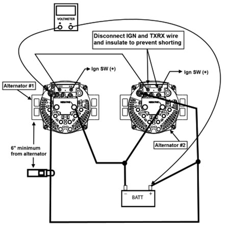
Fig 4
2) Make sure IGN. and TXRX wire to Alternator #2 is disconnected and insulated to prevent shorting.
Note: Make sure ammeter is at least 6” (15cm) away from the alternator to eliminate the possibility of faulty readings.
3) Operate engine at 1500 RPM.
Increase vehicle electrical loads by turning on accessories or by using a carbon pile connected
across the batteries until the alternator is producing 75% of its rated output. Use the ammeter to verify this output.
4) Record voltage on voltmeter. If reading is greater than .25V (12V system) or .5V (24V
system) then there is a problem with the positive cable.
Check cable condition and terminals for corrosion or loose connections. Do not continue until excessive voltage drop is resolved.
Alternator Negative Cable Test (Alternator 1)
1) Connect voltmeter and ammeter per Fig 5.
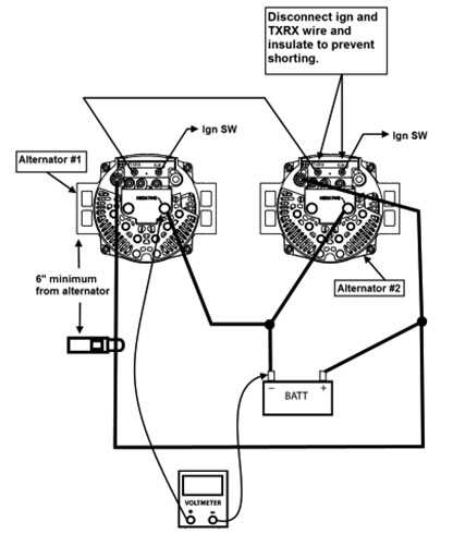
Fig 5
2) Make sure IGN. and TXRX wire to Alternator #2 is disconnected and insulated to prevent shorting.
Note: Make sure ammeter is at least 6” (15cm) away from the alternator to eliminate the possibility of faulty readings.
3) Operate engine at 1500 RPM.
Increase vehicle electrical loads by turning on accessories or by using a carbon pile connected across the batteries until the alternator is producing 75% of its rated output. Use the ammeter to verify this output.
4) Record voltage on voltmeter. If reading is greater than .25V (12V system) or .5V (24V system) then there is a problem with the negative cable.
Check cable condition and terminals for corrosion or loose connections. Do not continue until excessive voltage drop is resolved.
TXRX Circuit Test (Alternator 1)
1) Disconnect “TXRX” wire from both alternators.
2) Disconnect the ignition “IGN” wire from Alternator #2 and insulate to prevent shorting.
3) Connect voltmeter and ammeter per Fig 6.
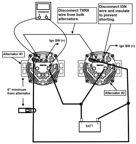
Fig 6
Set voltmeter to read DC
4) Start engine and operate at 1500 RPM
5) Increase vehicle electrical loads by turning on accessories or use a carbon pile connected across the batteries until the alternator is producing 50% of its rated output. Use ammeter to verify this output.
6) Record voltage on voltmeter. If voltage is between 3.2V-4.8V then TXRX circuit is working properly. If not then replace alternator or voltage regulator.
Alternator Performance Test No Load (Alternator 2)
1) Before you begin with the steps below, make sure the batteries have been properly tested and are at least 75% charged. Otherwise, any electrical tests you conduct on the charging system will be inaccurate.
With the surface charge removed from the batteries, battery voltage should be (12.45V or greater on 12V systems) and (24.9V or greater on 24V systems. If battery voltage is less than 12.45V or 24.9V charge or replace the batteries.
2) Connect voltmeter to Alternator #2 output terminals and ammeter to Alternator #2 positive output cable. Disconnect Alternator #1 ignition and TXRX wire and insulate to prevent shorting.
See Fig 7 for proper connection of voltmeter and ammeter.
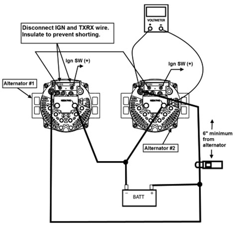
Fig 7
Note: Make sure ammeter is at least 6” (15cm) away from alternator to eliminate the possibility of faulty readings.
3) Make sure voltage is present at the alternator’s output terminals. If voltage is not present correct problem before proceeding.
4) Start engine and operate at 1500 RPM.
5) Check that all vehicle electrical loads are turned off and reading on ammeter is less than 20 amps. If reading is greater than 20 amps, double check that all vehicle loads are turned off and that the batteries are fully charged.
6) Record voltage on voltmeter. Reading should be between 13.8V-14.4V (12V system) and 27.8V-28.2V (24V system). If voltage is not within these values then the alternator is defective and must be replaced.
Alternator Performance Test Under Load (Alternator 2)
1) Keep engine running at 1500RPM and meters connected per Fig 7.

Fig 7
Increase vehicle electrical loads by turning on accessories or by using a carbon pile connected across the batteries until the alternator is producing 75% of its rated output. Use the ammeter to verify this output.
2) Record voltage on voltmeter. Compare reading to that taken during the (Alternator Performance Test No Load (Alternator 2)) step 6. If alternator voltage dropped more than .5V then the alternator is defective and needs to be replaced.
Alternator Positive Cable Test (Alternator 2)
1) Connect voltmeter and ammeter per Fig 8.
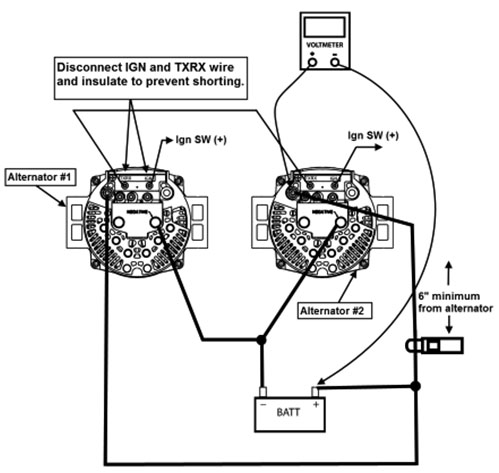
Fig 8
2) Make sure IGN. and TXRX wire to Alternator #1 is disconnected and insulated to prevent shorting.
Note: Make sure ammeter is at least 6” (15cm) away from the alternator to eliminate the possibility of faulty readings.
3) Operate engine at 1500 RPM.
Increase vehicle electrical loads by turning on accessories or by using a carbon pile connected across the batteries until the alternator is producing 75% of its rated output. Use the ammeter to verify this output.
4) Record voltage on voltmeter. If reading is greater than .25V (12V system) or .5V (24V system) then there is a problem with the positive cable.
Check cable condition and terminals for corrosion or loose connections. Do not continue until excessive voltage drop is resolved.
Alternator Negative Cable Test (Alternator 2)
1) Connect voltmeter and ammeter per Fig 9.
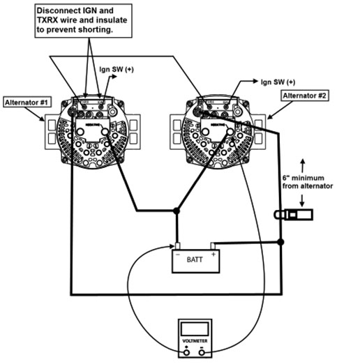
Fig 9
2) Make sure IGN. and TXRX wire to Alternator #1 is disconnected and insulated to prevent shorting.
Note: Make sure ammeter is at least 6” (15cm) away from the alternator to eliminate the possibility of faulty readings.
3) Operate engine at 1500 RPM.
Increase vehicle electrical loads by turning on accessories or by using a carbon pile connected across the batteries until the alternator is producing 75% of its rated output. Use the ammeter to verify this output.
4) Record voltage on voltmeter. If reading is greater than .25V (12V system) or .5V (24V system) then there is a problem with the negative cable.
Check cable condition and terminals for corrosion or loose connections. Do not continue until excessive voltage drop is resolved.
TXRX Circuit Test (Alternator 2)
1) Disconnect “TXRX” wire from both alternators.
2) Disconnect the ignition “IGN” wire from Alternator #1 and insulate to prevent shorting.
3) Connect voltmeter and ammeter per Fig 10.
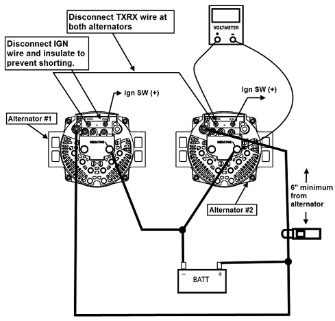
Fig 10
Set voltmeter to read DC
4) Start engine and operate at 1500 RPM
5) Increase vehicle electrical loads by turning on accessories or use a carbon pile connected across the batteries until the alternator is producing 50% of its rated output. Use ammeter to verify this output.
6) Record voltage on voltmeter. If voltage is between 3.2V-4.8V then TXRX circuit is working properly. If not then replace alternator or voltage regulator.
For more information on vehicle electrical systems, please check out the lots more information in RIBO Parts Articles. 


 Alternators


